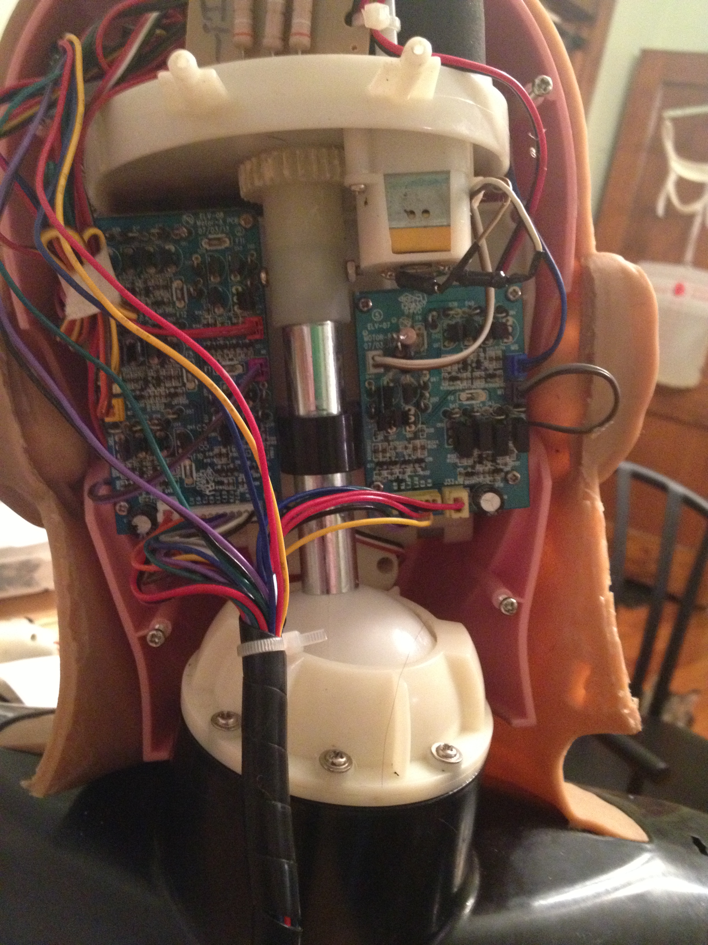
This is a view from within the head. Getting into this area requires removing the wig and ungluing skin. Getting in there is not so hard, but putting it back together is not going to be simple. One of the goals of my project is to make my controller work without having to get into this area. The only concer with that is the ADC board. The ADC board is using an 8 channel analog to digital IC, the Sonix SNAD01A. This chip is a bit odd. First of all, the interface to it is not standard. It isn’t complicated, but requires a custom driver and some bit-banging. Also, the 8th channel is different from the other 7. It is intended for battery voltage monitoring and reduces the input by 1/16th before connecting to the converter. For this reason, only the first 7 channels are actually being used here. The 8th channel (Head rotate) is routed down to the mainboard through the connector. So, another ADC is required for this 8th channel. This complicates the code of course, but simplifies the installation of the custom controller. I assume that someone will usually intend to change the character of the bust, so it is likely that they will get inside the head anyway. But, my overall design goal is to simply be plug and play.
 A very dark picture of the ADC board and its location. It is installed at the very top of the head. I have designed a different board to mount here that connects all 8 channels and uses an I2C chip (ADS7828E.) It was my original intention to use this replacement, but I want to see if I can do without it first.
A more detailed breakdown of the head will be forthcoming. I have one bust that I have tore down completely. So I will be taking pictures of the re-build process. Then you can get a look at all the various mechanisms in detail.
For now, let’s focus on control.
There will be 16 motor signals coming out of the head for the 8 motors. Every motor has 2 signals, such as Left and Right or Up and Down. Putting a logic high on one of these signals will move the motor in that direction. Obviously you should not put a logic high on both directions at the same time. There is no protection in the H-Bridges for that. So, be careful.
Two 9V feeds lead into the head. These are for the two H-Bridge boards.
The last connection is the ADC board. This 6 pin wiring harness includes VCC (3.3v) and ground, the leftover head rotate pot output, and the control signals for the Sonix ADC. These are DSC0, DSCLK, and DSIO. DSC0 is connected to START on the Sonix chip. This is a chip select. DSCLK is used to shift in or out the data on the DSIO line. The datasheet for the chip details the interface and timing. I won’t go into it here. But, it is essentially a set of commands to setup the chip and to do conversions. BTW, all signals are labeled on the mainboard (for everything.)
So, in summary…
We have 16 outputs needed for the motors, 3 control signals for the ADC, and one analog line to deal with. That’s 20 pins of a microcontroller, with one being an analog input.
