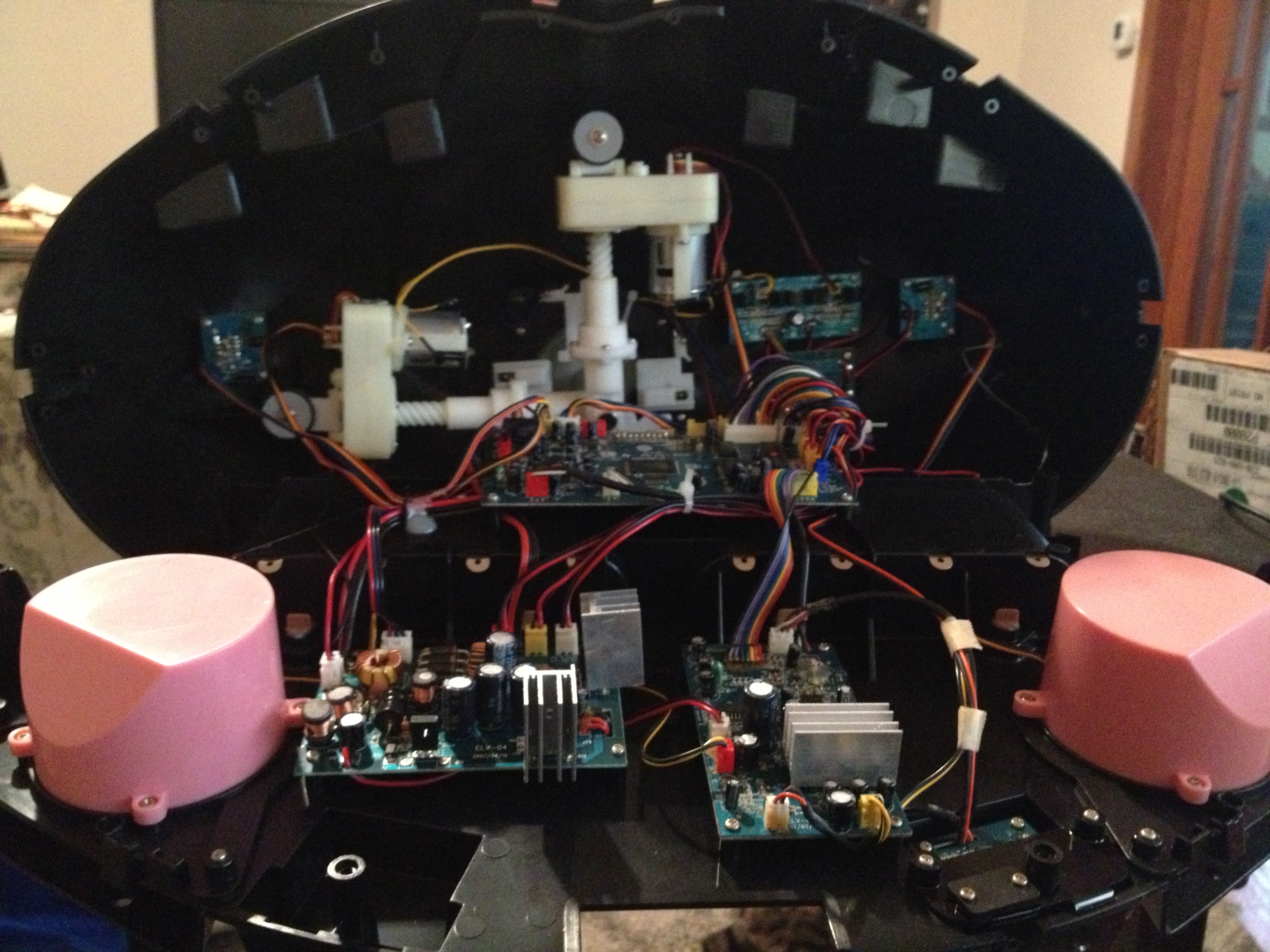
This is what you will be greeted with after removing the bottom of the bust. As you can see, there is a lot going on within there. Let’s look at some more photos showing some detail.
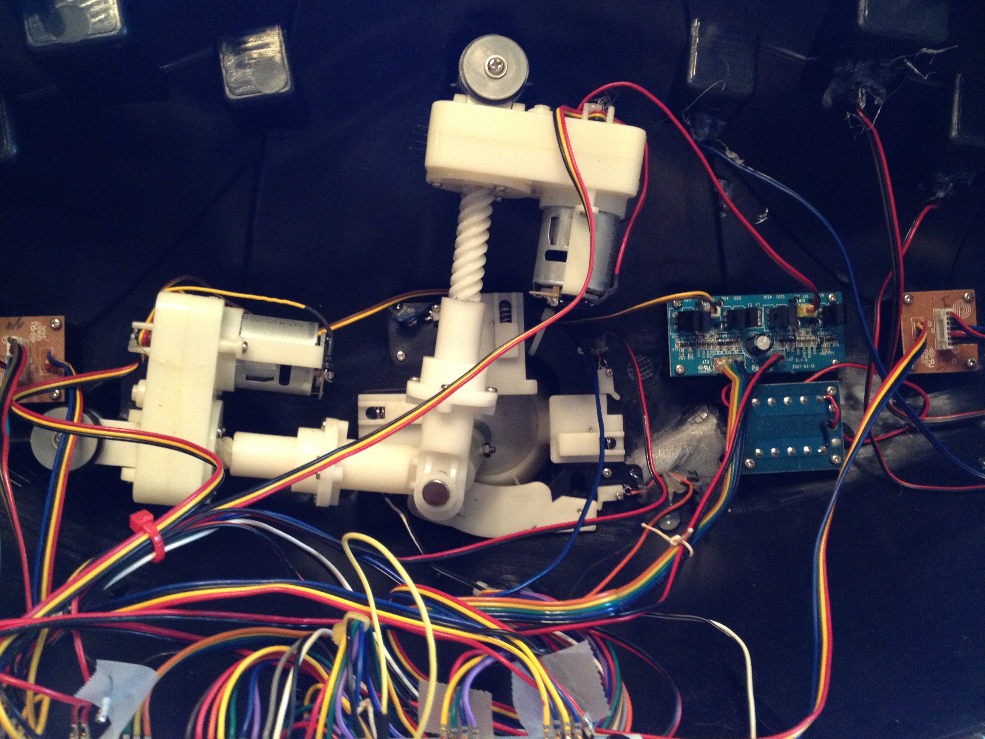
This is the Nod and Tilt mechanism up close. Looks like an inverted joystick.
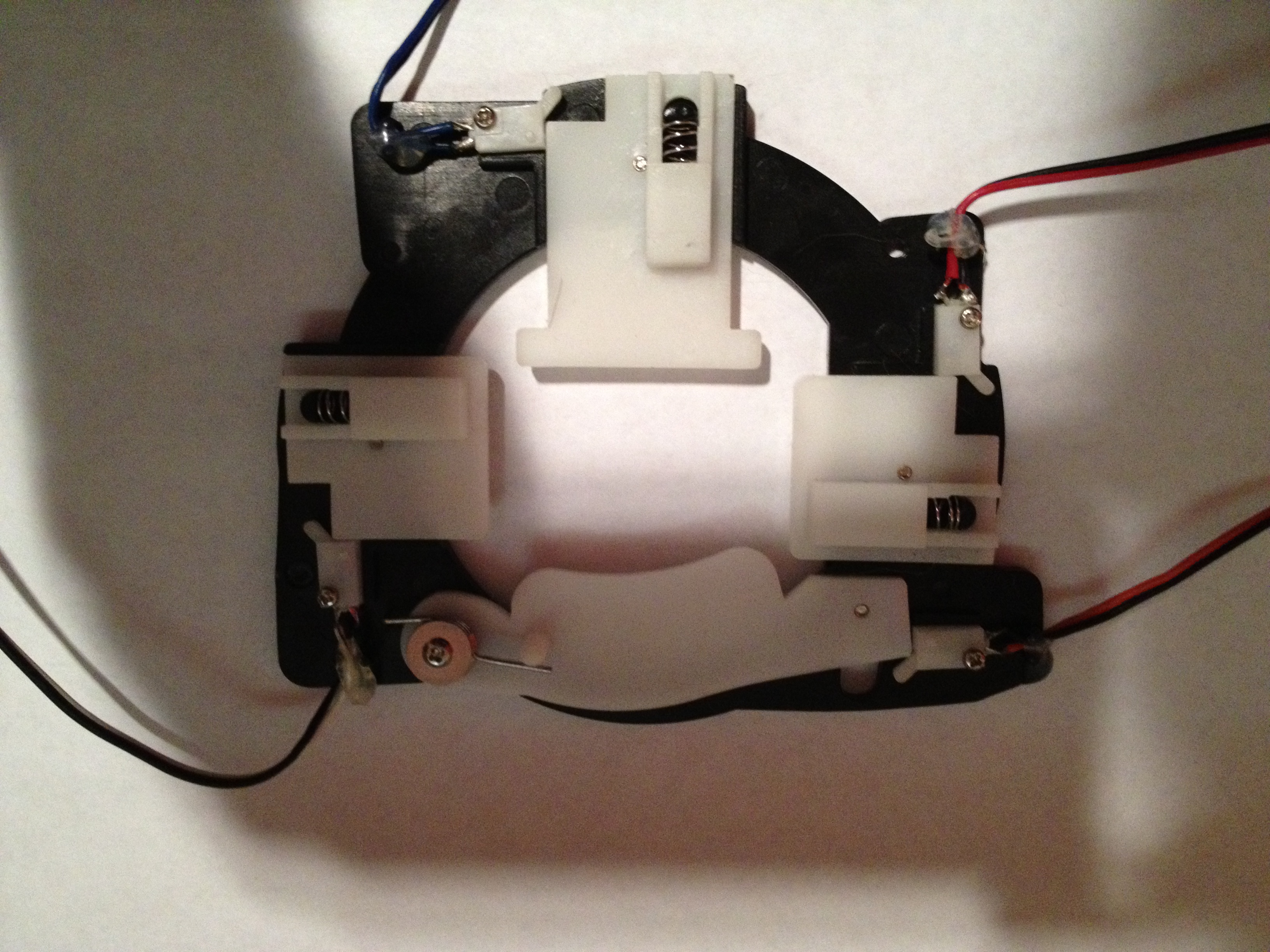
This is the limit switch mechanism removed. You can see the spring-loaded plates which push the various switches. The shortest side is the back of the neck. The switches are normally open. They need to be connected to pullup resistors. Open = logic HIGH, closed = logic LOW. The switches are activated when a direction has reached its extreme. These will be used to calibrate the encoders and to provide failsafes to stop the motors.
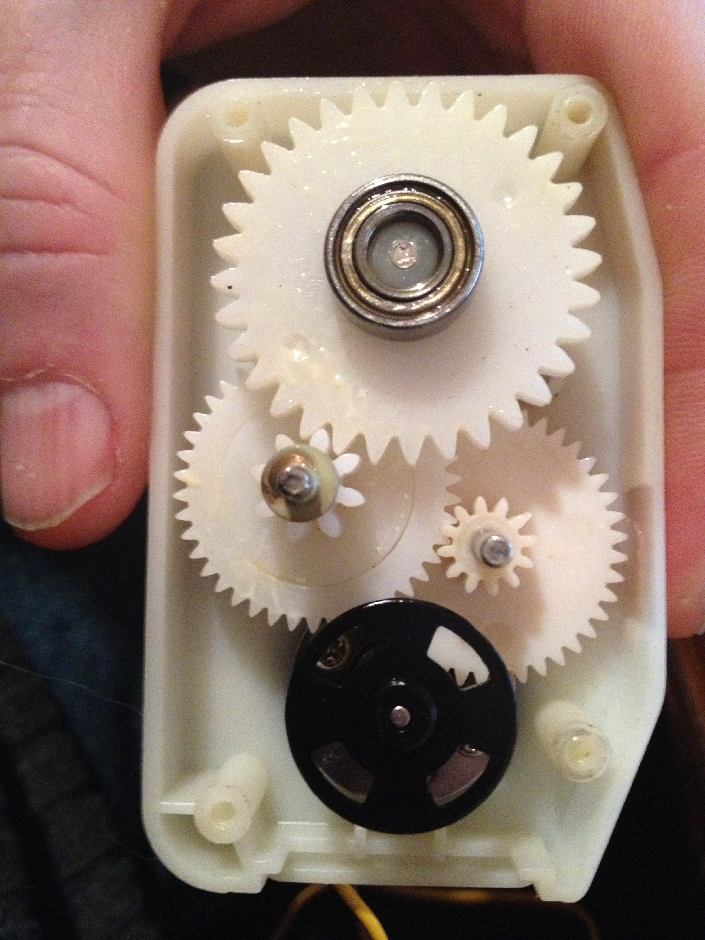
This is a picture taken inside the gearbox of one of the linear actuators. The encoder wheel is connected directly to the output shaft of the motor. It has 4 slots in it. Through testing, I have determined the gear ratio is 10 revolutions of the motor = 1 revolution of the output shaft of the leadscrew. That amounts to 5mm of linear travel. The full travel for the nod is 35mm and tilt is 55mm. Some basic math:
10 revolutions = 5mm, so 2 revolutions = 1mm. There will be 4 pulses per revolution. So 1mm = 8 pulses. Nod full travel should be 280 pulses, tilt = 440 pulses.
So let’s talk signals:
Within the neck we have 4 outputs for the motors, 2 inputs from the encoders, and 4 limit switch inputs. Total, we have 10 signals needed. The encoders should be connected to interrupt pins (T0 and T1 or INT0 and INT1?) The limit switches should also be connected to interrupt capable pins. I think PCINT (pin change interrupt) pins should work nicely.
We will go into the IR, audio etc… at a later time. The Mini-SSC controller will only deal with the motors.

Awesome info, very helpful! I have yet to disassemble the boxes, so it’s great to see them opened up and explained in detail.