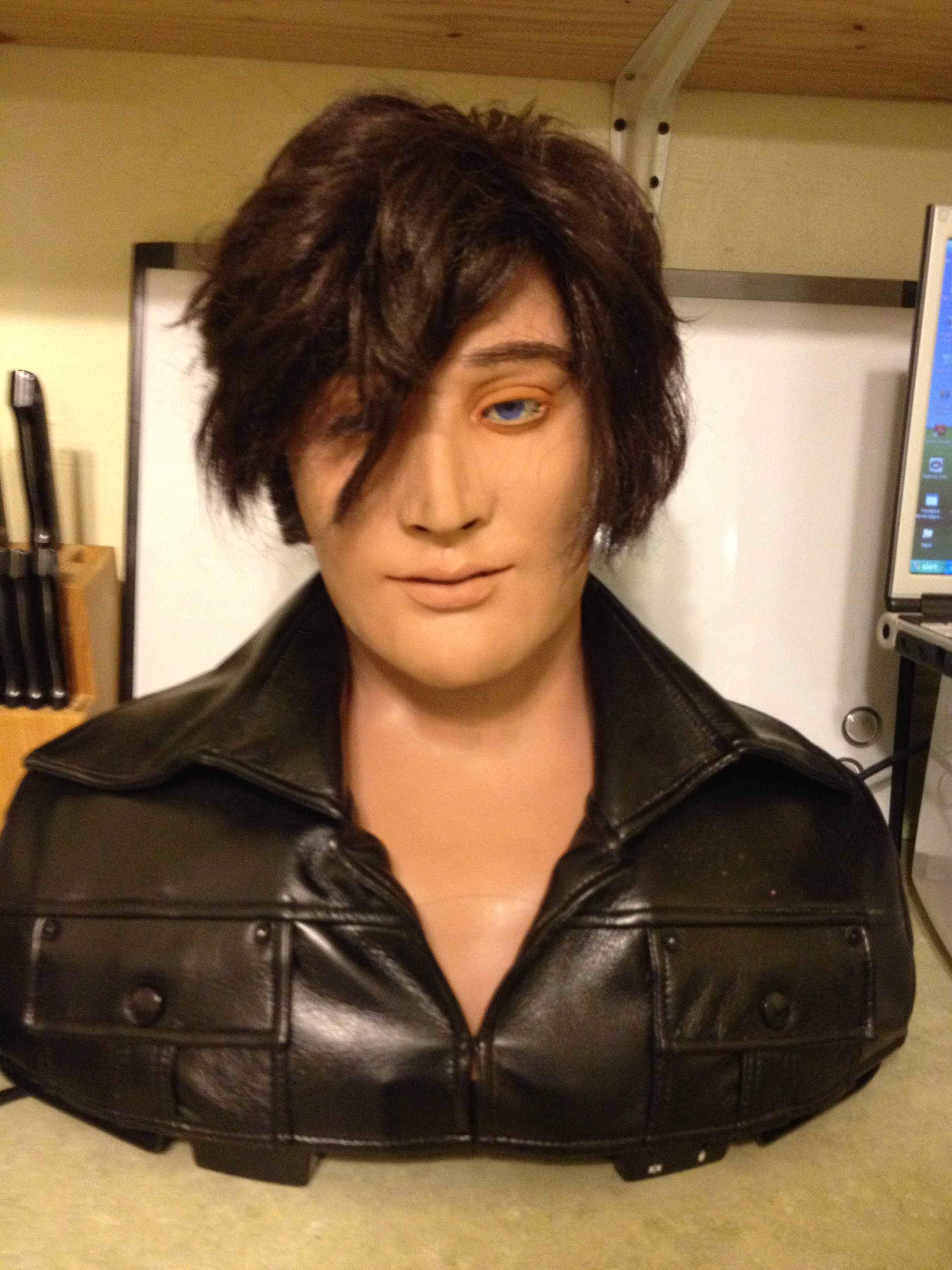
The goal of this project is to design, code, and build a new controller board for the Wowwee Alive Animatronic Elvis bust. These have been discontinued, but can still be found ocassionally through the usual trading means (eBay, etc..)
The interface will be a drop-in board which provides a Mini-SSC II (Serial Servo Controller) interface to all the motors in the bust. Additional hardware present in the bust are a IR motion tracking system, remote control, and an audio amplifier with digital volume control with 8 levels. These features will be not be controlled by this interface, with the exception of possibly controlling the volume using the same Mini-SSC commands using a channel.
My intended end-use is to install a RaspberryPi inside the bust along with the custom controller to make the bust standalone.
So, let’s start with a description of the Elvis hardware we are dealing with. I will break this down logically, and then additional posts will cover each piece in detail. I would also like to document a complete teardown and build-up of the bust including improvements and mods along the way. This will come later.
For now, out-of-the-box…
The bust contains 10 total DC motors controlling several movements:
Eyes Up/Down
Eyes Left/Right
Eyebrows U/D
Left Eyelids U/D
Right Eyelids U/D
Lip U/D
Jaw U/D
Head Rotate L/R
Head Tilt L/R
Head Nod U/D
We can seperate these motors by Head and Neck. “Head” refers to the area within the skull. Very difficult to get to. “Neck” refers to the area within the chest cavity. This area is very easy to get to by just removing the bottom panel.
Head:
The first 8 motors listed above are connected to potentiometers which track position. There is an ADC board (ELV-09) located at the very top of the head connected to these pots.
Neck:
Within the neck are the remaining two DC motors. Controlling these is a bit mor difficult. The two motors are arranged as linear actuators using a threaded rod. They control the XY directions of the head. Basically it is a head on a stick. Instead of using potentiometers, these motors are using encoder wheels positioned directly on the motor shafts within the gear box. These are not quadrature encoders, so no positional or directional control. At all 4 extremes of the XY movement there are limit switches which are triggered.
Also within the neck area are the following boards:
Power Supply. The power supply takes input from either a 9V wall wart or 8 D size batteries. The 9V is connected directly to the motor H-Bridge boards to run the motors. The power supply board steps down the 9V to 6V for the logic supply. Finally, there is a battery detection discrete which tells the controller whether batteries are installed or not.
Audio Amplifier. The audio amplifier handles several inputs and outputs and allows control between them all. The original bust included karaoke mode, which would play MP3s with no lyrics and amplify the audio coming from a microphone and mixing it with the audio from the mainboard. The audio amp also includes digital volume control with 8 levels. This is controlled by the mainboard.
Mainboard. This board is what we will be replacing. Another post will go into detail about the stock mainboard as a matter of interest. But for our purposes here, it is being completely removed from the bust.
All of the above boards are mounted on the baseplate. There are also several other boards mounted within the chest cavity. First is the H-Bridge board for the Nod and Tilt motors and a resistor board used for current limiting the motors. All H-bridge boards will have one of these boards attached. The boards for the IR tracking and remote reception are also located within the chest cavity. On each side of the chest, there are 2 IR transmitter LEDs and a 38KHz IR decoder. The IR transmitters are given a 38KHz burst and are reflected off objects in front of the bust. Using a system on the left and right allows the controller to know which direction to turn the head to follow a person.
This concludes the introduction to the project. Next will be a breakdown of the individual assemblies in greater detail.
