SNAD01 Library for Arduino

I am trying to write my first library for the Arduino and am having some trouble with it. The library is for the Sonix ADC chip SNAD01A. I used Tod E. Kurt’s ( as my base.

First, here is the compiler output:
SNAD01.cpp: In member function 'uint8_t SNAD01::SNAD01_Convert(uint8_t)':
SNAD01.cpp:113: error: 'SNAD01_sendChan' was not declared in this scope
SNAD01.cpp: In member function 'uint8_t SNAD01::SNAD01_readbit()':
SNAD01.cpp:245: error: '_DIOpinRegister' was not declared in this scope
SNAD01.cpp: At global scope:
SNAD01.cpp:269: error: no 'void SNAD01::SNAD01_sendChan(uint8_t)' member function declared in class 'SNAD01'
SNAD01.cpp:284: error: no 'void SNAD01::SNAD01_sendReg(uint8_t)' member function declared in class 'SNAD01'

But I can’t figure out what is wrong. Perhaps I am just going cross-eyed here. Could anyone lend a hand?
Here is my header:
/*
* SONIX SNAD01x Series ADC library for Arduino
* Modified version of SoftI2CMaster written by Tod E. Kurt, http://todbot.com/blog/
* Mod written by Scott McDonnell 01/2013
*/

#ifndef SNAD01_h
#define SNAD01_h

#include

#define _SNAD01_VERSION 0 // software version of this library

class SNAD01
{
private:
// per object data
uint8_t _DIOpin;
uint8_t _CLKpin;
uint8_t _STARTpin;
uint8_t _DIOBitMask;
uint8_t _CLKBitMask;
uint8_t _STARTBitMask;

volatile uint8_t *_DIOPortRegister;
volatile uint8_t *_CLKPortRegister;
volatile uint8_t *_STARTPortRegister;
volatile uint8_t *_DIOPortModeRegister;
volatile uint8_t *_CLKPortModeRegister;
volatile uint8_t *_STARTPortModeRegister;
volatile uint8_t *_DIOPinRegister;

// private methods
void setPins(uint8_t DIOpin, uint8_t CLKpin, uint8_t STARTpin);
void SNAD01_writebit( uint8_t c );
uint8_t SNAD01_readbit(void);
void SNAD01_start(void);
void SNAD01_stop(void);
void PulseClock(void);
void SNAD01_writebyte( uint8_t c );
uint8_t SNAD01_readbyte( );
void SNAD01_sendCMD(uint8_t c);
void SNAD01_SendChan(uint8_t c);
void SNAD01_SendReg(uint8_t c);

public:
// public methods
SNAD01(uint8_t DIOpin, uint8_t CLKpin, uint8_t STARTpin);
void SNAD01_init(uint8_t reg, uint8_t mode, uint8_t Wkup);
void SNAD01_PWRDN();
uint8_t SNAD01_Convert(uint8_t chan);
uint8_t SNAD01_getDigital();

};

#endif

And here is my library:
/*
* SONIX SNAD01x Series ADC Library for Arduino
* Modified version of SoftI2CMaster by Tod E. Kurt, http://todbot.com/blog/
* Mod written by scott McDonnell 01/2013
*/

#include "Arduino.h"
#include "pins_arduino.h"
#include "SNAD01.h"

#include
#include

#define SNAD01bitdelay 50

//Define commands (in binary)
#define cmd_Reg 0x60
#define cmd_PDN 0x00
#define cmd_wkup 0x40
#define cmd_attrib 0x20
#define cmd_conv 0x80
#define cmd_dig 0xa0

//_XXXPortModeRegister = DDR register
//_XXXPortRegister = Port data register
//_XXXPinRegister = Input Register

//macro for setting DIO pin HIGH
#define SNAD01_DIO_hi() \
*_DIOPortModeRegister &=~ _DIOBitMask; \
*_DIOPortRegister |= _DIOBitMask;

//macro for setting DIO pin Low
#define SNAD01_DIO_lo() \
*_DIOPortRegister &=~ _DIOBitMask; \
*_DIOPortModeRegister |= _DIOBitMask;

//Macro for setting CLK pin HIGH
#define SNAD01_CLK_hi() \
*_CLKPortModeRegister &=~ _CLKBitMask; \
*_CLKPortRegister |= _CLKBitMask;

//Macro for setting CLK pin Low
#define SNAD01_CLK_lo() \
*_CLKPortRegister &=~ _CLKBitMask; \
*_CLKPortModeRegister |= _CLKBitMask;

//Macro for setting START pin HIGH
#define SNAD01_start_hi() \
*_STARTPortRegister &=~ _STARTBitMask; \
*_STARTPortModeRegister |= _STARTBitMask;

//Macro for setting START pin Low
#define SNAD01_start_lo() \
*_STARTPortRegister &=~ _STARTBitMask; \
*_STARTPortModeRegister |= _STARTBitMask;

//Macro for setting DIO as input
#define SNAD01_DIO_IN() \
*_DIOPortModeRegister |= _DIOBitMask;

//Macro for setting DIO pin as output
#define SNAD01_DIO_OUT() \
*_DIOPortModeRegister &=~ _DIOBitMask;

//
// Constructor
//

//Usage: ADC = SNAD01(2,3,4); DIO = pin 2, CLK = pin 3, START = pin 4
SNAD01::SNAD01(uint8_t DIOpin, uint8_t CLKpin, uint8_t STARTpin)
{
setPins(DIOpin, CLKpin, STARTpin);
}

//****************************************************************
//External Functions
//****************************************************************

//Usage: ADC.SNAD_init(reg,attrib,wkup);
void SNAD01::SNAD01_init(uint8_t reg, uint8_t attrib, uint8_t wkup)
{
//Write registers
//Write attributes
//Write wkup

// //I2C_PORT &=~ (_BV( I2C_SDA ) | _BV( I2C_SCL ));
// *_CLKPortRegister &=~ (_DIOBitMask | _CLKBitMask);

// SNAD01_CLK_hi();
// SNAD01_DIO_hi();

_delay_us(SNAD01bitdelay);
}

void SNAD01::SNAD01_PWRDN(){
//Prepare for power down (set RF and MB bits to 0)
//send cmd for powerdown (0x000b)
}

//--------------------------------------------------------------------
//Get Readings (Digital and Analog Routines)
//--------------------------------------------------------------------
uint8_t SNAD01::SNAD01_Convert(uint8_t chan){
//Send command for analog conversion
//read one byte and return byte

uint8_t res;

SNAD01_start();
SNAD01_sendCMD(cmd_conv);
SNAD01_sendChan(chan);
SNAD01_CLK_hi();
SNAD01_CLK_lo();
//SNAD01_DIO_IN;
SNAD01_CLK_hi();
SNAD01_CLK_lo();
res=SNAD01_readbyte();
SNAD01_stop();

return res;

}

uint8_t SNAD01::SNAD01_getDigital(){
//send command for digital reading
//read one byte, return byte

uint8_t res;

SNAD01_start();
SNAD01_sendCMD(cmd_dig);
res=SNAD01_readbyte();
SNAD01_stop();

return res;
}

//***************************************************************
//Internal Functions
//***************************************************************

//--------------------------------------------------------------------
//Set pins and register configuration
//--------------------------------------------------------------------
//
// Turn Arduino pin numbers into PORTx, DDRx, and PINx
//
void SNAD01::setPins(uint8_t DIOpin, uint8_t CLKpin, uint8_t STARTpin)
{
//Define pins for CLK, START, DIO

uint8_t port;

_DIOpin = DIOpin;
_CLKpin = CLKpin;
_STARTpin = STARTpin;

_DIOBitMask = digitalPinToBitMask(DIOpin);
_CLKBitMask = digitalPinToBitMask(CLKpin);
_STARTBitMask = digitalPinToBitMask(STARTpin);

port = digitalPinToPort(CLKpin);
_CLKPortRegister = portOutputRegister(port);
_CLKPortModeRegister = portModeRegister(port);

port = digitalPinToPort(DIOpin);
_DIOPortRegister = portOutputRegister(port);//Port Register
_DIOPortModeRegister = portModeRegister(port); //DDR register
_DIOPinRegister = portInputRegister(port);//Pin Register (input)

port = digitalPinToPort(STARTpin);
_STARTPortRegister = portOutputRegister(port);
_STARTPortModeRegister = portModeRegister(port);

}
// START Conditions
//
void SNAD01::SNAD01_start(void)
{

// set both to high at the same time
//I2C_DDR &=~ (_BV( I2C_SDA ) | _BV( I2C_SCL ));

SNAD01_DIO_lo();//set to low before switching between input to output
// *_DIOPortModeRegister &=~ (_DIOBitMask); //Set DIO DDR as output

SNAD01_DIO_OUT();

_delay_us(SNAD01bitdelay);

SNAD01_start_lo();
_delay_us(SNAD01bitdelay);

}

// STOP Conditions
//
void SNAD01::SNAD01_stop(void)
{
SNAD01_start_hi();//deactivate chip select
_delay_us(SNAD01bitdelay);

SNAD01_DIO_lo(); //set DIO to low before switching directions

SNAD01_DIO_IN(); //set DIO for input (HIz)
_delay_us(SNAD01bitdelay);
}

void SNAD01::SNAD01_writebit( uint8_t c )
{

if ( c > 0 ) {
SNAD01_DIO_hi();
} else {
SNAD01_DIO_lo();
}

PulseClock();

// if ( c > 0 ) {
// SNAD01_DIO_lo();
// }

_delay_us(SNAD01bitdelay);

}

//
uint8_t SNAD01::SNAD01_readbit(void)
{

SNAD01_DIO_lo();//set dio pin low before switching directions
SNAD01_DIO_IN(); //set to input

SNAD01_CLK_hi();
_delay_us(SNAD01bitdelay);

uint8_t port = digitalPinToPort(_DIOpin);
volatile uint8_t* pinReg = portInputRegister(port);
uint8_t c = *pinReg;

SNAD01_CLK_lo();

_delay_us(SNAD01bitdelay);

return ( c & _DIOBitMask) ? 1 : 0;
}

void SNAD01::SNAD01_sendCMD(uint8_t c )
{
SNAD01_start();

for ( uint8_t i=0;i<3;i++)
{
SNAD01_writebit( c & 128 );

c<<=1;
}

SNAD01_stop();

}

void SNAD01::SNAD01_sendChan(uint8_t c )
{
SNAD01_start();

for ( uint8_t i=0;i<3;i++)
{
SNAD01_writebit( c & 128 );

c<<=1;
}

SNAD01_stop();

}

void SNAD01::SNAD01_sendReg(uint8_t c )
{
SNAD01_start();

for ( uint8_t i=0;i<4;i++)
{
SNAD01_writebit( c & 128 );

c<<=1;
}

SNAD01_stop();

}

// write a byte to theSNAD01
//
void SNAD01::SNAD01_writebyte( uint8_t c )
{
SNAD01_start();

for ( uint8_t i=0;i<8;i++)
{
SNAD01_writebit( c & 128 );

c<<=1;
}

SNAD01_stop();
}

// read a byte from the SNAD01
//
uint8_t SNAD01::SNAD01_readbyte( )
{
uint8_t res = 0;

SNAD01_start();

for ( uint8_t i=0;i<8;i++)
{
res <<= 1;
res |= SNAD01_readbit();
}

_delay_us(SNAD01bitdelay);

SNAD01_stop();

return res;

}

void SNAD01::PulseClock(){
//Send one clock transition

SNAD01_CLK_lo();
_delay_us(SNAD01bitdelay);
SNAD01_CLK_hi();
_delay_us(SNAD01bitdelay);
}
Prototyping

All of the connectors used in the elvis bust that we want access to are JST PH connectors which are 2mm pitched. Obviously, this is not breaboard friendly. There are a few options here. You can remove the pins from the JST headers and snap them onto a .100 header or you can insert small wire into the JST headers directly and extend them. I started out by doing option 1, but that introduces some challenges. First, you had better have good notes of wire colors and keep track of the various harnesses. Second, the length of the cabling was only meant to plug into the mainboard which was positioned high up within the chest area. I was orginally supporting the bust off the bench and arranging a breadboard beneath it. This makes it a bit difficult to access the wiring for changes. I am in the process of re-doing this to extend the cabling out to the front using the first option. I will be using some multi-colored ribbon cable which will match the wire colors in most cases (the wiring typically follows resistor color coding.)

The next consideration is powering everything. You need a hefty 9V for the motors and H-bridge boards, 3.3v for the various sensors and logic supply. If you use the power supply from the Elvis, there is a 6V output on the harness going to the mainboard which you can connect to a 3.3V regulator. Also, the Arduino has a 3.3v out but I have not determine if it is enough to handle the load of the various sensors.

The limit switches need to use pullup resistors (the internal pullups in the AVR are fine) and should be debounced. The switches used are very cheap and are vary noisey. They also have a tendency to short out or open. We will be replacing these with better switches in a future post. A very small value cap should stablize things enough for our purposes.

You need to use a polarized cap across the power supply close to the encoder signals. If you don’t, they will be very noisey.. Inside the photo-interrupter board, there is a 330 ohm resistor in series with the IR LED. At 3.3v this will provide 10ma, at 5v will provide 15ma. 15ma should be safe, but keep that in mind if powering everything with 5v.

The voltage used by the Elvis bust was 3.3v and an arduino uses 5V standard (unless you mod it!) So, there may be some issues with driving the H-Bridges directly from the arduino. A series resistor would likely be all that is needed here. I need to check the exact value. I think that I damaged one H-bridge board already, but I think that was from accidentally turning on both directions of a motor at the same time during testing. It didn’t completely stop running, but that particular motor is sluggish now. I took the H-bridges for granted in the beginning, but now that I replaced the sluggish board, I will do some reverse engineering on it. A future enhancement may be to replace the H-Bridge boards with H-BRIDGE ICs that can source more current.

Finally a note on the 9V power adapter. I am not convinced that it is really big enough to handle everything. Especially when adding the Raspberry Pi. I will be looking into replacing this with a heftier 12V adapter.

Since I am in the process of re-arranging my prototyping set up, I will add some pictures in a future post.

Mini-SSC Emulator

As mentioned in the beginning, the goal of this project is to provide a Mini-SSC II interface to all of the motors in the bust. Mini-SSC II is a Serial Servo Control standard. It was the first such serial servo controller offered by Scott Edwards many moons ago (and is still being made.) It has become the standard for hobby level animatronics control as well as some professional stuff.

The protocol is very simple. Each channel requires 3 bytes . The first byte is always 255, which tells the servo controller that what follows will be servo commands. This allows other serial traffic to co-exist on the same port. Servo can be 0-254 and indicates the servo channel to command. Pos can be 0-254 and indicates the position you wish to move the servo to.

This provides the front end of the controller. Normally the Mini-SSC would be controlling actual servos which have all the smarts in them for position control. You would simply provide a pulse width indicating the position you wish to move to. The servo electronics would translate this to movement and hold that movement. Here we need a “back-end” which simulates the servo electronics as well.

Our code needs to distinguish between the channels requested and the different methods of controlling the motors (or the volume control.) The various methods again are:

2 neck motors. Using encoders and limit switches for position control
7 head/face motors using potentiometers and a SNAD01 ADC for position control
1 head/face motor (Head Rotate) using the internal ADC of the microcontroller for position control

If we add in the volume control, we need 1 select line and 3 lines to choose one of 8 volume levels. I will be investigating re-using the limit switch lines to do this as it shouldn’t be used very often.

The code will run a timer to refresh the motors in order to hold their positions. The typical servo controller does this at 50Hz. We can probably get away with slower since the movements are pretty solid and shouldn’t move on their own. The exceptions are a few movements that will spring back when power is removed from the motors. These are the jaw, lip, and eyebrows. Up/Down control of these motors move them from center.

A feature I would like to add is a console interface. The mode (Mini-SSC II and Console) will be selected by a switch at startup. The console interface will allow testing and debugging.

The basic loop here is to update the current position, compare demanded position, and determine the direction of travel. In order to hold the servos, the last demanded position will be kept.

Upon power up, the controller will run the motors through a calibration sequence and move everything to a nuetral position. It will then hold those positions waiting for commands to come in.

I am testing the various modules using an arduino mostly for the ease of prototyping. The final code will be written in C (but hey, if the arduino is capable of pulling it all off, I may just stay with that.)
My target intially was the ATMega32. Using an I2C ADC chip allowed exactly enough IO and resources. The final target will be decided as I get further into the project. I am using an ArduinoMega2560 for prototyping. It is probably overkill for this project and since it does not come in a DIP package, it may be difficult for others to follow along without having a custom board made.

Head

Elvis 009

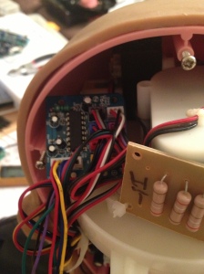
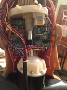
This is a view from within the head. Getting into this area requires removing the wig and ungluing skin. Getting in there is not so hard, but putting it back together is not going to be simple. One of the goals of my project is to make my controller work without having to get into this area. The only concer with that is the ADC board. The ADC board is using an 8 channel analog to digital IC, the Sonix SNAD01A. This chip is a bit odd. First of all, the interface to it is not standard. It isn’t complicated, but requires a custom driver and some bit-banging. Also, the 8th channel is different from the other 7. It is intended for battery voltage monitoring and reduces the input by 1/16th before connecting to the converter. For this reason, only the first 7 channels are actually being used here. The 8th channel (Head rotate) is routed down to the mainboard through the connector. So, another ADC is required for this 8th channel. This complicates the code of course, but simplifies the installation of the custom controller. I assume that someone will usually intend to change the character of the bust, so it is likely that they will get inside the head anyway. But, my overall design goal is to simply be plug and play.

Elvis 008 A very dark picture of the ADC board and its location. It is installed at the very top of the head. I have designed a different board to mount here that connects all 8 channels and uses an I2C chip (ADS7828E.) It was my original intention to use this replacement, but I want to see if I can do without it first.

A more detailed breakdown of the head will be forthcoming. I have one bust that I have tore down completely. So I will be taking pictures of the re-build process. Then you can get a look at all the various mechanisms in detail.

For now, let’s focus on control.

There will be 16 motor signals coming out of the head for the 8 motors. Every motor has 2 signals, such as Left and Right or Up and Down. Putting a logic high on one of these signals will move the motor in that direction. Obviously you should not put a logic high on both directions at the same time. There is no protection in the H-Bridges for that. So, be careful.

Two 9V feeds lead into the head. These are for the two H-Bridge boards.

The last connection is the ADC board. This 6 pin wiring harness includes VCC (3.3v) and ground, the leftover head rotate pot output, and the control signals for the Sonix ADC. These are DSC0, DSCLK, and DSIO. DSC0 is connected to START on the Sonix chip. This is a chip select. DSCLK is used to shift in or out the data on the DSIO line. The datasheet for the chip details the interface and timing. I won’t go into it here. But, it is essentially a set of commands to setup the chip and to do conversions. BTW, all signals are labeled on the mainboard (for everything.)

So, in summary…

We have 16 outputs needed for the motors, 3 control signals for the ADC, and one analog line to deal with. That’s 20 pins of a microcontroller, with one being an analog input.

Neck

Elvis 011

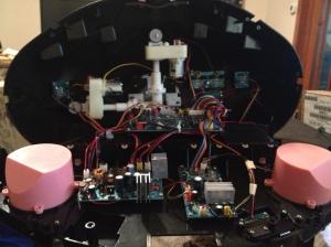
This is what you will be greeted with after removing the bottom of the bust. As you can see, there is a lot going on within there. Let’s look at some more photos showing some detail.

Elvis 006

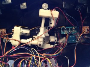
This is the Nod and Tilt mechanism up close. Looks like an inverted joystick.

Elvis 004

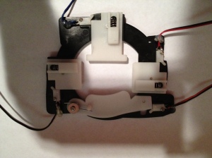
This is the limit switch mechanism removed. You can see the spring-loaded plates which push the various switches. The shortest side is the back of the neck. The switches are normally open. They need to be connected to pullup resistors. Open = logic HIGH, closed = logic LOW. The switches are activated when a direction has reached its extreme. These will be used to calibrate the encoders and to provide failsafes to stop the motors.

Elvis 002

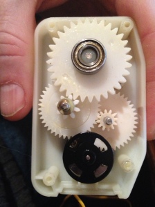
This is a picture taken inside the gearbox of one of the linear actuators. The encoder wheel is connected directly to the output shaft of the motor. It has 4 slots in it. Through testing, I have determined the gear ratio is 10 revolutions of the motor = 1 revolution of the output shaft of the leadscrew. That amounts to 5mm of linear travel. The full travel for the nod is 35mm and tilt is 55mm. Some basic math:

10 revolutions = 5mm, so 2 revolutions = 1mm. There will be 4 pulses per revolution. So 1mm = 8 pulses. Nod full travel should be 280 pulses, tilt = 440 pulses.

So let’s talk signals:

Within the neck we have 4 outputs for the motors, 2 inputs from the encoders, and 4 limit switch inputs. Total, we have 10 signals needed. The encoders should be connected to interrupt pins (T0 and T1 or INT0 and INT1?) The limit switches should also be connected to interrupt capable pins. I think PCINT (pin change interrupt) pins should work nicely.

We will go into the IR, audio etc… at a later time. The Mini-SSC controller will only deal with the motors.

Project Scope

meetme 033

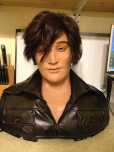
The goal of this project is to design, code, and build a new controller board for the Wowwee Alive Animatronic Elvis bust. These have been discontinued, but can still be found ocassionally through the usual trading means (eBay, etc..)

The interface will be a drop-in board which provides a Mini-SSC II (Serial Servo Controller) interface to all the motors in the bust. Additional hardware present in the bust are a IR motion tracking system, remote control, and an audio amplifier with digital volume control with 8 levels. These features will be not be controlled by this interface, with the exception of possibly controlling the volume using the same Mini-SSC commands using a channel.

My intended end-use is to install a RaspberryPi inside the bust along with the custom controller to make the bust standalone.

So, let’s start with a description of the Elvis hardware we are dealing with. I will break this down logically, and then additional posts will cover each piece in detail. I would also like to document a complete teardown and build-up of the bust including improvements and mods along the way. This will come later.

For now, out-of-the-box…

The bust contains 10 total DC motors controlling several movements:

Eyes Up/Down
Eyes Left/Right
Eyebrows U/D
Left Eyelids U/D
Right Eyelids U/D
Lip U/D
Jaw U/D
Head Rotate L/R
Head Tilt L/R
Head Nod U/D

We can seperate these motors by Head and Neck. “Head” refers to the area within the skull. Very difficult to get to. “Neck” refers to the area within the chest cavity. This area is very easy to get to by just removing the bottom panel.

Head:
The first 8 motors listed above are connected to potentiometers which track position. There is an ADC board (ELV-09) located at the very top of the head connected to these pots.

Neck:
Within the neck are the remaining two DC motors. Controlling these is a bit mor difficult. The two motors are arranged as linear actuators using a threaded rod. They control the XY directions of the head. Basically it is a head on a stick. Instead of using potentiometers, these motors are using encoder wheels positioned directly on the motor shafts within the gear box. These are not quadrature encoders, so no positional or directional control. At all 4 extremes of the XY movement there are limit switches which are triggered.

Also within the neck area are the following boards:

Power Supply. The power supply takes input from either a 9V wall wart or 8 D size batteries. The 9V is connected directly to the motor H-Bridge boards to run the motors. The power supply board steps down the 9V to 6V for the logic supply. Finally, there is a battery detection discrete which tells the controller whether batteries are installed or not.

Audio Amplifier. The audio amplifier handles several inputs and outputs and allows control between them all. The original bust included karaoke mode, which would play MP3s with no lyrics and amplify the audio coming from a microphone and mixing it with the audio from the mainboard. The audio amp also includes digital volume control with 8 levels. This is controlled by the mainboard.

Mainboard. This board is what we will be replacing. Another post will go into detail about the stock mainboard as a matter of interest. But for our purposes here, it is being completely removed from the bust.

All of the above boards are mounted on the baseplate. There are also several other boards mounted within the chest cavity. First is the H-Bridge board for the Nod and Tilt motors and a resistor board used for current limiting the motors. All H-bridge boards will have one of these boards attached. The boards for the IR tracking and remote reception are also located within the chest cavity. On each side of the chest, there are 2 IR transmitter LEDs and a 38KHz IR decoder. The IR transmitters are given a 38KHz burst and are reflected off objects in front of the bust. Using a system on the left and right allows the controller to know which direction to turn the head to follow a person.

This concludes the introduction to the project. Next will be a breakdown of the individual assemblies in greater detail.